Showing posts with label to. Show all posts
Showing posts with label to. Show all posts
Thursday, April 11, 2013
How to Lights Control for Model Cars
The author gave his partner a radio controlled (RC) model car as a gif t. She found it a lot of fun, but thought that adding realistic lights would be a definite improvement. So the author went back to his shed, plugged in his soldering iron, and set to work equipping the car with realistic indicators, headlights, tail lights and brake lights.
Lights Control for Model Cars Circuit Diagram

The basic idea was to tap into the signal from the radio control receiver and, with a bit of help from a microcontroller, simulate indicators using flashing yellow LEDs and brake lights using red LEDs. Further red LEDs are used for the tail lights, and white LEDs for the headlights. Connectors JP4 and JP5 (channel 0) are wired in parallel, as are JP6 and JP7 (channel 1), allowing the circuit to be inserted into the servo control cables for the steering and drive motor respectively. The ATtiny45 micro-controller takes power from the radio receiver via diode D1. T1 and T2 buffer the servo signals to protect IC1’s inputs from damage.
IC1 analyses the PWM servo signals and gen-erates suitable outputs to switch the LEDs via the driver transistors. T3 drives the two left indicators (yellow), T4 the two right indica-tors, and T5 the brake LEDs (red). The red tail lights (JP2-8 and JP2-8) and the white head-lights (JP2-9 and JP2-10) are lit continuously. The brake lights are driven with a full 20 mA, so that they are noticeably brighter than the tail lights, which only receive 5 mA. If you wish to combine the functions of tail light and brake light, saving t wo red LEDs, sim-ply connect pin 10 of JP2 to pin 14 and pin 12 to pin 16. Then connect the two combined brake/tail LEDs either at JP2-5 and JP2-6 or at JP2-7 and JP2-8.
JP3 is provided to allow the use of a separate lighting supply. This can either be connected to an additional four-cell battery pack or to the main supply for the drive motor. The val-ues given for resistors R8 to R17 are suitable for use with a 4.8 V supply. JP2 can take the form of a 2x10 header.
As usual the sof t ware is available as a free download from the Elektor web pages accom-panying this article[1], and ready-programmed microcontrollers are also available. The microcontroller must be taught what servo signals correspond to left and right turns, and to full throttle and full braking. First connect the fin-ished circuit to the radio control electronics in the car, making sure everything is switched of f. Fit jumper JP1 to enable configuration mode, switch on the radio control transmit-ter, set all proportional controls to their cen-tre positions, and then switch on the receiver. The indicator LEDs should first flash on both sides. Then the car will indicate left for 3 s: during this time quickly turn the steering on the radio control transmitter fully to the left and the throt tle to full reverse (maximum braking).
Hold the controls in this position until the car starts to indicate right. Then set the controls to their opposite extremes and hold them there until both sides flash again. Now, if the car has an internal combustion engine (and so cannot go in reverse), keep the throttle control on full; if the car has an electric motor, set the throttle to full reverse. Hold this position while both sides are flashing. Configuration is now complete and JP1 can be removed. If you make a mistake during the configuration process, start again from the beginning. link
JP3 is provided to allow the use of a separate lighting supply. This can either be connected to an additional four-cell battery pack or to the main supply for the drive motor. The val-ues given for resistors R8 to R17 are suitable for use with a 4.8 V supply. JP2 can take the form of a 2x10 header.
As usual the sof t ware is available as a free download from the Elektor web pages accom-panying this article[1], and ready-programmed microcontrollers are also available. The microcontroller must be taught what servo signals correspond to left and right turns, and to full throttle and full braking. First connect the fin-ished circuit to the radio control electronics in the car, making sure everything is switched of f. Fit jumper JP1 to enable configuration mode, switch on the radio control transmit-ter, set all proportional controls to their cen-tre positions, and then switch on the receiver. The indicator LEDs should first flash on both sides. Then the car will indicate left for 3 s: during this time quickly turn the steering on the radio control transmitter fully to the left and the throt tle to full reverse (maximum braking).
Hold the controls in this position until the car starts to indicate right. Then set the controls to their opposite extremes and hold them there until both sides flash again. Now, if the car has an internal combustion engine (and so cannot go in reverse), keep the throttle control on full; if the car has an electric motor, set the throttle to full reverse. Hold this position while both sides are flashing. Configuration is now complete and JP1 can be removed. If you make a mistake during the configuration process, start again from the beginning. link

Tuesday, April 9, 2013
6 to 12 Volt Converter
Below its a converter circuit voltage from 6 Volt to 12 Volt DC.
 |
| 6 Volt to 12 Volt DC |
Part List :
R1, R4 2 .2K 1/4W Resistor
R2, R3 4.7K 1/4W Resistor
R5 1K 1/4W Resistor
R6 1.5K 1/4W Resistor
R7 33K 1/4W Resistor
R8 10K 1/4W Resistor
C1,C2 0.1uF Ceramic Disc Capacitor
C3 470uF 25V Electrolytic Capcitor
D1 1N914 Diode
D2 1N4004 Diode
D3 12V 400mW Zener Diode
Q1, Q2, Q4 BC547 NPN Transistor
Q3 BD679 NPN Transistor
L1 See Notes
Notes
1. L1 is a custom inductor wound with about 80 turns of 0.5mm magnet wire around a toroidal core with a 40mm outside diameter.
2. Different values of D3 can be used to get different output voltages from about 0.6V to around 30V. Note that at higher voltages the circuit might not perform as well and may not produce as much current. You may also need to use a larger C3 for higher voltages and/or higher currents.
3. You can use a larger value for C3 to provide better filtering.
4. The circuit will require about 2A from the 6V supply to provide the full 800mA at 12V.
Saturday, April 6, 2013
Frequency to Voltage Converter
Overview of IC LM2917 as Frequency to Voltage Converter
 Very easy to apply in measuring the output frequency with the formulation of single-chip Frequency to Voltage Converter VOUT = FIN x VCC x R1 x C1. Then the single-chip LM2917 Frequency to Voltage Converter This configuration requires only the RC only in frequncy doublings. And has an internal zener regulator to aimlessly accuracy and stability in frequency-to-voltage conversion process.
Continue reading...
IC LM2917 IC chip is designed specifically as a Frequency to Voltage Converter or Frequency to Voltage converter. In its use to applications Frequency to Voltage Converter IC LM2917 requires few external components.
There are several examples of applications of Frequency to Voltage Converter IC LM2917 is supplied in the LM2917 IC datahseet. In this article series Frequency to Voltage Converter IC also taken from the LM2917 datasheet. The advantages of single chip LM2917 Frequency to Voltage Converter is able to provide instantaneous volt output o at time of frequency change 0 Hz.
There are several examples of applications of Frequency to Voltage Converter IC LM2917 is supplied in the LM2917 IC datahseet. In this article series Frequency to Voltage Converter IC also taken from the LM2917 datasheet. The advantages of single chip LM2917 Frequency to Voltage Converter is able to provide instantaneous volt output o at time of frequency change 0 Hz.
Very easy to apply in measuring the output frequency with the formulation of single-chip Frequency to Voltage Converter VOUT = FIN x VCC x R1 x C1. Then the single-chip LM2917 Frequency to Voltage Converter This configuration requires only the RC only in frequncy doublings. And has an internal zener regulator to aimlessly accuracy and stability in frequency-to-voltage conversion process. |
| Frequency to Voltage Converter |
Feature-owned single-chip LM2917 Frequency to Voltage Converter
- Reference to ground directly with variable reluctance
- Op Amp / Comparator with transistor output
- 50 mA maximum output currents for application directly to the load
- Frequency doubling untul low ripel
- Buid in zener
- Linear output ± 0.3%
Application single chip LM2917 Frequency to Voltage Converter
- Frequency to Voltage Converter
- Rotation speed sensor applications
- Speedometer
- Tachometer
- Cruise Control
- Cluth Control
And other application associated with the measurement of rotation speed or frequency measurements.
Friday, April 5, 2013
Make this Automatic 10 Watt to 1000 Watt LED Emergency Light Circuit
The following post explains a very simple yet an outstanding automatic 1 watt to 1000 watt emergency lamp circuit. The circuit also includes an automatic over voltage and low voltage battery shut off feature.
The entire circuit functioning may be understood with the following points:
Referring the below given circuit diagram, the transformer, bridge and the associated 100uF/25V capacitor forms a standard step down AC to DC power supply circuit.
The bottom SPDT relay is directly connected with the above power supply output such that it remains activated when mains is connected with the circuit.
In the above situation, the N/O contacts of the relay stay connected which keeps the LED shut OFF (since its connected with the N/C of the relay).
This takes care of the LED switching, making sure than the LEDs are switched ON only in the absence of mains power.
However, the positive from the battery is not directly connected with the LED module, rather it comes via another relay N/O contacts (the upper relay). This relay is integrated with a high/low voltage sensor circuit stationed for detecting the battery voltage conditions.
Supposing the battery is in a discharged condition, switching ON the mains keeps the relay deactivated so that the the rectified DC can reach the battery via the upper relay N/C contacts initiating the charging process of the connected battery.
When the battery voltages reaches the "full charge" potential, as per the setting of the 10 K preset, the relay trips and joins with the battery through its N/O contacts.
Now in the above situation if the mains fails, the LED module is able to get powered via the above relay and the lower relay N/O contacts and get illuminated.
Since relays are used, the power handling capacity becomes sufficiently high. The circuit is thus able to support in excess of 1000 watts of power (lamp), provided the relay contacts are appropriately rated for the preferred load.

The entire circuit functioning may be understood with the following points:
Referring the below given circuit diagram, the transformer, bridge and the associated 100uF/25V capacitor forms a standard step down AC to DC power supply circuit.
The bottom SPDT relay is directly connected with the above power supply output such that it remains activated when mains is connected with the circuit.
In the above situation, the N/O contacts of the relay stay connected which keeps the LED shut OFF (since its connected with the N/C of the relay).
This takes care of the LED switching, making sure than the LEDs are switched ON only in the absence of mains power.
However, the positive from the battery is not directly connected with the LED module, rather it comes via another relay N/O contacts (the upper relay). This relay is integrated with a high/low voltage sensor circuit stationed for detecting the battery voltage conditions.
Supposing the battery is in a discharged condition, switching ON the mains keeps the relay deactivated so that the the rectified DC can reach the battery via the upper relay N/C contacts initiating the charging process of the connected battery.
When the battery voltages reaches the "full charge" potential, as per the setting of the 10 K preset, the relay trips and joins with the battery through its N/O contacts.
Now in the above situation if the mains fails, the LED module is able to get powered via the above relay and the lower relay N/O contacts and get illuminated.
Since relays are used, the power handling capacity becomes sufficiently high. The circuit is thus able to support in excess of 1000 watts of power (lamp), provided the relay contacts are appropriately rated for the preferred load.
Tuesday, March 26, 2013
How to Make a Capacitive Discharge Ignition
How to Make a Capacitive Discharge Ignition (CDI) Circuit for Two-Wheelers
The ignition process in any vehicle becomes the heart of the entire system as without this stage the vehicle just won’t start. To initiate the process, earlier we use to have the circuit breaker unit for the required actions.
Nowadays a more efficient and long lasting mechanism has been developed for the ignitions in vehicles, called the capacitor discharge ignition system. It incorporate an electronic circuit precisely functions like the old contact breaker, but in a solid-state electronic manner.
Let’s learn the circuit operations with the following points:
Basically as the name suggest, ignition system in vehicles refers to the process in which the fuel mixture is ignited for initiating the engine and the drive mechanisms.
This ignition is done through an electrical process by generating high voltage electrical arcs.
The above electrical arc is created through extreme high voltage passage across two potentially opposite conductors through the enclosed air gap.
As we all know that for generating high voltages we require some kind of stepping up process, generally done through transformers.
As the source voltage available in two wheeler vehicles is from an alternator, may not be powerful enough for the functions.
Therefore the voltage needs to be stepped up many thousand folds in order to reach the desired arcing level.
The ignition coil, which is very popular and we all have seen them in our vehicles is especially designed for the above stepping up of the input source voltage
However the voltage from the alternator cannot be directly fed to the ignition coil because the source may be low in current, therefore we employ a CDI unit or a capacitive discharge unit for collecting and releasing the alternator power in succession in order to make the output compact and high with current.
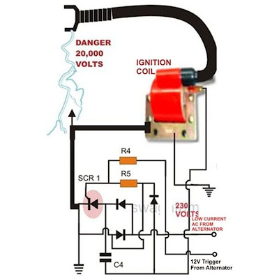
Referring to the above capacitor discharge ignition circuit diagram, we see a simple configuration consisting of a few diodes, resistors, a SCR and a single high voltage capacitor.
The input to the CDI unit is derived from two sources of the alternator.
One source is a low voltage around 12 volts while the other input is taken from the relatively high voltage tap of the alternator, generating around a 100 volts.
The 100 volts input is suitably rectified by the diodes and converted to 100 volts DC. This voltage is stored inside the high voltage capacitor instantaneously.
The low 12 voltage signal is applied to the triggering stage and used for triggering the SCR.
The SCR responds to the half wave rectified voltage and switches the capacitors ON and OFF alternately.
Now since the SCR is integrated to the ignition primary coil, the released energy from the capacitor is forcibly dumped in the primary winding of the coil.
The action generates a magnetic induction inside the coil and the input from the CDI which is high in current and voltage is further enhanced to extremely high levels at the secondary winding of the coil.
The generated voltage at the secondary of the coil may rise up to the level of many tens of thousands of volts.
This output is appropriately arranged across two closely held metal conductors inside the spark plug.
The voltage being very high in potential starts arcing across the points of the spark plug, generating the required ignition sparks for the ignition process.
Parts List for the CIRCUIT DIAGRAM
R4 = 56 Ohms,
R5 = 100 Ohms,
C4 = 1uF/250V
SCR = BT151 recommended.
All Diodes = 1N4007
Coil = Standard two-wheeler ignition Coil
Subscribe to:
Posts (Atom)