Showing posts with label 1000. Show all posts
Showing posts with label 1000. Show all posts
Friday, April 12, 2013
1000 Watt Power Amplifier
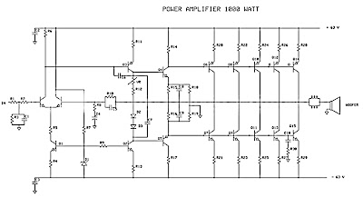
Power amplifier has up to 1000 Watt power, this circuit made one channel only so if you want to create a stereo in it must be made one again, actually this is more suitable power amplifier in use for Sound System or outdoor, so if only in use for the house I think is less suitable.
Maybe youve seen or even have an active speaker and there is written 1500 watts PMPO (Peak Music Power Output), make no mistake this is different from Power Amplifier Active Speaker, I often dismantle such Active Speaker in it only a power with power no more than 150 watts by using the transformer 2-3 Ampere. PMPO is not a real power which is issued by the Power Amplifier, but counting all the speakers that there is, for example: if there are 5 pieces of speakers on each channel and each speaker has a power of 10 W then it is 100 W PMPO.
Maybe youve seen or even have an active speaker and there is written 1500 watts PMPO (Peak Music Power Output), make no mistake this is different from Power Amplifier Active Speaker, I often dismantle such Active Speaker in it only a power with power no more than 150 watts by using the transformer 2-3 Ampere. PMPO is not a real power which is issued by the Power Amplifier, but counting all the speakers that there is, for example: if there are 5 pieces of speakers on each channel and each speaker has a power of 10 W then it is 100 W PMPO.
 |
| 1000W Power Amplifier schematics |
 |
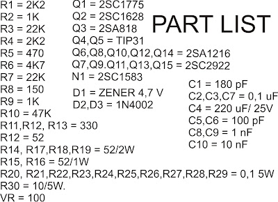
| Part List 1000W amplifier |
While this 1000 Watt Power Amplifier minimal use transformer 20 Ampere. And the output of Power Amplifier DC voltage contains approximately 63 volts, with currents and voltages of this magnitude, this 1000 Watt Power Amplifier will not hesitate hesitate to destroy your woofer speakers to connect. To overcome that then before the speaker on connects to 1000 Watt Power Amplifier must be in pairs Speaker Protector.
Actually if you want to create a Power Amplifier with great power does not have to make a Power Amplifier with great power. Example: you want to create a Power Amplifier with 10 000 Watt power. You do not have to assemble a Power Amplifier with power of 10,000 watts, but you assemble the power Power Amplifier Small but many, such as you assemble the Power Amplifier with 1000 Watts of power for as many as 10 pieces, it will produce 10 000 Watt Power Amplifier helpless.
Circuit uses power transistors pair of 5 x 5 x 2SA1216 and 2SC2922 and 2SC1583 use a differential amplifier that actually contains 2 pieces of transistors that are in containers together. Why use such built-in amplifier differental tujuanya so identical / similar, could have uses 2 separate transistors but can result in amplifier so it is not symmetrical.
Tips combining speaker.
To get the speakers with great power combining techniques can be used in parallel series, combining each group of speakers should sepaker they will have the same impedance, the same type (Woofer, Mid Range or tweeter) and the same power. Number of merging these speakers should consists of 4 , 9, 16 ff, see picture
 |
| Speaker wiring |
Example: The number of speakers have 4 pieces each of its 200 Watt power generated will be a speaker at = 200 x 4 = 800 Watt. If there are 9 speakers 200 W then the result = 9 x 200 W = 1800 Watt.
Friday, April 5, 2013
Make this Automatic 10 Watt to 1000 Watt LED Emergency Light Circuit
The following post explains a very simple yet an outstanding automatic 1 watt to 1000 watt emergency lamp circuit. The circuit also includes an automatic over voltage and low voltage battery shut off feature.
The entire circuit functioning may be understood with the following points:
Referring the below given circuit diagram, the transformer, bridge and the associated 100uF/25V capacitor forms a standard step down AC to DC power supply circuit.
The bottom SPDT relay is directly connected with the above power supply output such that it remains activated when mains is connected with the circuit.
In the above situation, the N/O contacts of the relay stay connected which keeps the LED shut OFF (since its connected with the N/C of the relay).
This takes care of the LED switching, making sure than the LEDs are switched ON only in the absence of mains power.
However, the positive from the battery is not directly connected with the LED module, rather it comes via another relay N/O contacts (the upper relay). This relay is integrated with a high/low voltage sensor circuit stationed for detecting the battery voltage conditions.
Supposing the battery is in a discharged condition, switching ON the mains keeps the relay deactivated so that the the rectified DC can reach the battery via the upper relay N/C contacts initiating the charging process of the connected battery.
When the battery voltages reaches the "full charge" potential, as per the setting of the 10 K preset, the relay trips and joins with the battery through its N/O contacts.
Now in the above situation if the mains fails, the LED module is able to get powered via the above relay and the lower relay N/O contacts and get illuminated.
Since relays are used, the power handling capacity becomes sufficiently high. The circuit is thus able to support in excess of 1000 watts of power (lamp), provided the relay contacts are appropriately rated for the preferred load.

Subscribe to:
Posts (Atom)