Showing posts with label power. Show all posts
Showing posts with label power. Show all posts
Sunday, May 5, 2013
Simple Dual Voltage Power Supply 12 Volt
This is the simple circuit diagram of Dual Voltage Power Supply. It is used for Misc… application. This circuit is called regulated power supply. For this reason the main component of this circuit is Regulator IC. It also needs few components to built. The regulator 7812 is the positive voltage regulator and 7912 is the negative voltage regulator.

You can also use 7809 for 9 volt positive power supply and 7909 for negative voltage power supply. It regulates voltage from 24Volt to 12 Volt (DC). The transformer input is 110Volt to 220Volt (AC) and the output must be between 12Volt to 24Volt (AC) and current must be 500mA. In this circuit some capacitors are used as a filter for removing repole.

Friday, April 12, 2013
Using LTC3601 3 3V DC Power Converter
This Dc power converter circuit is designed LTC3601 from Linear Technology and is capable to up to 1.5A output current at a 3.3V. The LTC3601 operating supply voltage range is from 4V to 15V making it suitable for a wide range of power supply applications. The operating frequency of the LTC3601 buck regulator is programmable from 800kHz to 4MHz with an external resistor enabling the use of small surface mount inductors.

The LTC3601 buck regulator can operate in two modes: Burst Mode operation and forced continuous mode to allow the user to optimize output voltage ripple, noise, and light load efficiency for a given application.
1000 Watt Power Amplifier
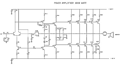
Power amplifier has up to 1000 Watt power, this circuit made one channel only so if you want to create a stereo in it must be made one again, actually this is more suitable power amplifier in use for Sound System or outdoor, so if only in use for the house I think is less suitable.
Maybe youve seen or even have an active speaker and there is written 1500 watts PMPO (Peak Music Power Output), make no mistake this is different from Power Amplifier Active Speaker, I often dismantle such Active Speaker in it only a power with power no more than 150 watts by using the transformer 2-3 Ampere. PMPO is not a real power which is issued by the Power Amplifier, but counting all the speakers that there is, for example: if there are 5 pieces of speakers on each channel and each speaker has a power of 10 W then it is 100 W PMPO.
Maybe youve seen or even have an active speaker and there is written 1500 watts PMPO (Peak Music Power Output), make no mistake this is different from Power Amplifier Active Speaker, I often dismantle such Active Speaker in it only a power with power no more than 150 watts by using the transformer 2-3 Ampere. PMPO is not a real power which is issued by the Power Amplifier, but counting all the speakers that there is, for example: if there are 5 pieces of speakers on each channel and each speaker has a power of 10 W then it is 100 W PMPO.
 |
| 1000W Power Amplifier schematics |
 |
| Part List 1000W amplifier |
While this 1000 Watt Power Amplifier minimal use transformer 20 Ampere. And the output of Power Amplifier DC voltage contains approximately 63 volts, with currents and voltages of this magnitude, this 1000 Watt Power Amplifier will not hesitate hesitate to destroy your woofer speakers to connect. To overcome that then before the speaker on connects to 1000 Watt Power Amplifier must be in pairs Speaker Protector.
Actually if you want to create a Power Amplifier with great power does not have to make a Power Amplifier with great power. Example: you want to create a Power Amplifier with 10 000 Watt power. You do not have to assemble a Power Amplifier with power of 10,000 watts, but you assemble the power Power Amplifier Small but many, such as you assemble the Power Amplifier with 1000 Watts of power for as many as 10 pieces, it will produce 10 000 Watt Power Amplifier helpless.
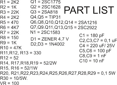
Circuit uses power transistors pair of 5 x 5 x 2SA1216 and 2SC2922 and 2SC1583 use a differential amplifier that actually contains 2 pieces of transistors that are in containers together. Why use such built-in amplifier differental tujuanya so identical / similar, could have uses 2 separate transistors but can result in amplifier so it is not symmetrical.
Tips combining speaker.
To get the speakers with great power combining techniques can be used in parallel series, combining each group of speakers should sepaker they will have the same impedance, the same type (Woofer, Mid Range or tweeter) and the same power. Number of merging these speakers should consists of 4 , 9, 16 ff, see picture
 |
| Speaker wiring |
Example: The number of speakers have 4 pieces each of its 200 Watt power generated will be a speaker at = 200 x 4 = 800 Watt. If there are 9 speakers 200 W then the result = 9 x 200 W = 1800 Watt.
Wednesday, April 10, 2013
5 Volt Switching Regulator Power Supply
The switching regulator power supply used LM2575-5.0 on this schematic. You can make the stable voltage by using the 3 terminal regulator like LM317. However, because the output electric current and the inputted electric current are the same approximately, the difference between the input electric power (The input voltage x The input electric current) and the output power (The output voltage x The output current) is consumed as the heat with the regulator. Because it is, the efficiency isn�t good.

Data sheet for LM2575
SIMPLE SWITCHER 1A Step-Down Voltage Regulator
http://www.national.com/pf/LM/LM2575.htm
Monday, April 8, 2013
LM3886 High Performance Audio Power Amplifier
Audio Power Amplifier is an important part in sound reproduction ina sound system. Audio Power Amplifier with this power IC LM 3886Audio Power Amplifier is a highly capable and able to produce68 Watt power avg. 4Ohm load and capable of producing power 38 Watt8Ohm load.
With good sound reproduction capabilities of 20Hz-20kHz also possessed this LM3886 Audio Power Amplifier. Audio Power Amplifier LM3886 Speaker is equipped with protection that will protect the circuit output from over-voltage, under-voltage, over-loads, a short circuit power supply, thermal run-away and the temperature peak. Audio Power Amplifier LM3886 also equipped with noise reduction that can keep the audio system from noise well.
 |
| Schematic power amplifier with LM3886 |
Feature owned LM3886 Audio Power Amplifier
- 68W cont. avg. output power into 4Ω at VCC = ± 28V
- 38W cont. avg. output power into 8Ω at VCC = ± 28V
- 50W cont. avg. output power into 8Ω at VCC = ± 35V
- 135W instantaneous peak output power capability
- Signal-to-Noise Ratio ≥ 92dB
- An input mute function
- Output protection from a short to ground or to the supplies via internal current limiting circuitry
- Output over-voltage protection against transients from inductive loads
- Supply under-voltage protection, not allowing internal biasing to occur Pls | VEE | + | VCC | ≤ 12V, Thus eliminating turn-on and turn-off transients
- 11-lead TO-220 package
- Wide supply range 20V - 94V
Application of Audio Power Amplifier LM3886
- Stereo audio system
- Active Speaker
- High End Audio Power TV
- Suround Power Amplifier
Sunday, April 7, 2013
USB Power Injector
Create USB PowerInjector for GSM Modem Maximizing and stabilization USB voltage .
 Sometimes we need also to extend the USB cable connection. Usually cable so the store is no more or less than one meter. If the cable is good quality automatic reduction of voltage and current remain so flash media or a modem to function remained normal.
Sometimes the two media are not readable because of a decline in flow due to cable resistance is very large, so that lost power wasted.
Continue reading...
Sometimes we need also to extend the USB cable connection. Usually cable so the store is no more or less than one meter. If the cable is good quality automatic reduction of voltage and current remain so flash media or a modem to function remained normal.Sometimes the two media are not readable because of a decline in flow due to cable resistance is very large, so that lost power wasted.
 |
| USB injector circuit |
If this happens often flash or USB modem off often error-disconnected. To overcome this decrease in voltage performance. The principle is quite very simple. You simply "inject" is indeed voltage VCC 5VDC needed a modem or a flash.
 |
| Finishing USB inject |
After using the USB power injector is expected regardless of the length of external cable fixed voltage maximum. The principle works is simple enough original 5VDC voltage of the CPU / your computer off and then injected external voltage that has been prepared. IC (integrated circuits) AN 7805 was instrumental once that is out and stabilize the voltage between 4.8 to 5.2 VDC and the current required at least 500mA.
Saturday, April 6, 2013
Stereo TDA2822 audio power amplifier circuit

In this series I use IC tda2822M as the main amplifier, but if you want to use in addition to IC TDA2822M you can use ic I mentioned this is KA2209, NJM2073, U2822B, U2823B. Output is issued no more than 4W, which had low output. Supply voltage from 3 volts to 16 volts.
Below its schematics of TDA2822 stereo audio power amplifier

R1 = 4.7R
R2 = 4.7R
C1 = 1uF
C2 = 100uF
C3 = 100uF
C4 = 0.1uF
C5 = 470uF
C6 = 1uF
C7 = 100uF
C8 = 0.1uF
C7 = 100uF
C8 = 0.1uF
C9 = 470uF
ICs = KA2209 , NJM2073 , TDA2822 , U2822B , U2823B
Tuesday, April 2, 2013
Simple Automatic Switch For Audio Power Amplifier
Circuit of an automatic switch for audio power amplifier stage is presented here. The circuit uses stereo preamplifier output to detect the presence of audio to switch the audio power amplifier on only when audio is present. The circuit thus helps curtail power wastage. IC1 is used as an inverting adder. The input signals from left and right channels are combined to form a common signal for IC2, which is used as an open loop comparator. IC3 (NE556) is a dual timer. Its second section, i.e., IC3(b), is configured as monostable multivibrator. Output of IC3(b) is used to switch the power amplifier on or off through a Darlington pair formed by transistors T1 and T2. IC3(a) is used to trigger the monostable multivibrator whenever an input signal is sensed.
Circuit diagram:

Automatic Switch For Audio Power Amplifier Circuit Diagram
Under ‘no signal’ condition, pin 3 of IC2 is negative with respect to its pin 2. Hence the output of IC2 is low and as a result output of IC3(a) is high. Since there is no trigger at pin 8 of IC3(b), the output of IC3(b) will be low and the amplifier will be off. When an input singal is applied to IC1, IC2 converts the inverted sum of the input signals into a rectangular waveform by comparing it with a constant voltage which can be controlled by varying potentiometer VR1. When the output of IC2 is high, output pin 5 of IC3 goes low, thus triggering the monostable multivibrator. As soon as the audio input to IC1 stops, pin 5 of IC3 goes high and pin 1 of IC3 discharges through capacitor C3, thus resetting the monostable multivibrator.
Hence, as long as input signals are applied, the amplifier remains ‘on.’ When the input signals are removed, i.e., when signal level is zero, the amplifier switches off after the mono flip-flop delay period determined by the values of resistor R8 and capacitor C3. If no input signals are sensed within this time, the amplifier turns off—else it remains on. Power supply for the circuit can be obtained from the power supply of the amplifier. Hence, the circuit can be permanently fitted in the amplifier box itself. The main switch of the amplifier should be always kept on. Resistors R1 and R2 are used to divide single voltage supply into two equal parts.
Capacitors C1 and C2 are used as regulators and also as an AC bypass for input signals. Diode D1 is used so that loading fluctuations in power amplifier do not affect circuit regulation. Transisitor T2 acts as a high voltage switch which may be replaced by any other high voltage switching transistor satisfying amplifier current requirements. Value of resistor R10 should be modified for large current requirement. The LED glows when the amplifier is on. The circuit is very useful and relieves one from putting the amplifier on and off every time one plays a cassette or radio etc.
http://streampowers.blogspot.com/2012/06/simple-automatic-switch-for-audio-power_11.html
Monday, April 1, 2013
RF power amplifier IC
RF power amplifier IC is a type of electronic amplifier used to convert low-power radio frequency signal into a larger signal strength is important, usually for driving a transmitting antenna. This is usually optimized for high-efficiency, high output power (P1dB) of compression, loss of income on the input and output, better benefits, and optimal heat dissipation.
 |
| RF power amplifier IC |
To make our amplifiers can also use transistors or IC OP Amp. In the op amp is actually a transistor that is in the form of a series so its easier to use.
Suppose that is used in the amplifier IC Op Amp 741 is a monolithic high performance electronic components that use Fairchild epitacial process. IC Op Amp 741 is an IC in which packed a differential circuit. The data sheet of IC Op Amp 741.
Friday, March 29, 2013
Non Contact Power Monitor Circuit
This is a design circuit for non-contact AC power monitor for home appliances and laboratory equipment that should remain continuously switched-on. This circuit is built around CMOS IC CD4011 utilizing only a few components. NAND gates N1 and N2 of the IC are wired as an oscillator that drives a piezo buzzer directly. This is the figure of the circuit;

Resistors R2 and R3 and capacitor C2 are the oscillator components. The amplifier comprising transistors T1 and T2 disables the oscillator when mains power is available. In the standby mode, the base of T1 picks up 50Hz mains hum during the positive half cycles of AC and T1 conducts. This provides base current to T2 and it also conducts, pulling the collector to ground potential. As the collectors of T1 and T2 are connected to pin 2 of NAND gate N1 of the oscillator, the oscillator gets disabled when the transistors conduct. Capacitor C1 prevents rise of the collector voltage of T2 again during the negative half cycles. When the power fails, the electrical field around the equipment’s wiring ceases and T1 and T2 turn off. Capacitor C1 starts charging via R1 and preset VR and when it gets sufficiently charged, the oscillator is enabled and the piezo buzzer produces a shrill tone. Resistor R1 protects T2 from short circuit if VR is adjusted to zero resistance. The circuit can be easily assembled on a perforated/breadboard. Use a small plastic case to enclose the circuit and a telescopic antenna as aerial. A 9V battery can be used to power the circuit. Since the circuit draws only a few microamperes current in the standby mode, the battery will last several months.
Thursday, March 21, 2013
1 5 35 Volt DC Regulated Power Supply
Here is the circuit diagram of regulated power supply. It is a small power supply that provides a regulated voltage, adjustable between 1.5 and 35 volts at 1 ampere. This circuit is ready to use, you just need to add a suitable transformer. This circuit is thermal overload protected because the current limiter and thermal overload protection are included in the IC.
Picture of the circuit:

Circuit diagram:

Transformer selection chart:

Parts:
IC = LM317
P1 = 4.7K
R1 = 120R
C1 = 100nF - 63V
C2 = 1uF - 35V
C3 = 10uF - 35V
C4 = 2200uF - 35V
D1-D4 = 1N4007
Features:
Specifications :
Technical Specifications
Note:
Picture of the circuit:

1A Regulated Power Supply Circuit Schematic
Circuit diagram:

1A Regulated Power Supply Circuit Diagram
Transformer selection chart:

Transformer selection Guide-Table For Power Supply
Parts:
IC = LM317
P1 = 4.7K
R1 = 120R
C1 = 100nF - 63V
C2 = 1uF - 35V
C3 = 10uF - 35V
C4 = 2200uF - 35V
D1-D4 = 1N4007
Features:
- Just add a suitable transformer (see table)
- Great to power your projects and save money on batteries
- Suitable as an adjustable power supply for experiments
- Control DC motors, low voltage light bulbs, …
Specifications :
- Preset any voltage between 1.5 and 35V
- Very low ripple (80dB rejection)
- Short-circuit, thermal and overload protection
- Max input voltage : 28VAC or 40VDC
- Max dissipation : 15W (with heatsink)
- Dimensions : 52x52mm (2.1” x 2.1”)
Technical Specifications
- Input Voltage = 40Vdc max Transformer
- Output Voltage = 1.5V to 35Vdc
- Output Current = 1.5 Amps max.
- Power Dissipation = 15W max (cooled)
Note:
- It has not to be cooled if used for small powers. 28 Volt AC max is allowed for the input voltage.
Low Power Voltage Reference
The present reference is a special application of current source IC Type LM334. It has a tiny temperature coefficient and draws only a minute current: at room temperature, only 10 µA, which increases with large rises in temperature by only a few µA. The circuit is basically a bandgap reference, because the positive temperature coefficient of the LM334 is combined with the negative temperature coefficient of the base-emitter junction of a transistor (which ensures good thermal coupling). To obtain a temperature coefficient of zero, or very nearly so, the output voltage of the circuit is adjusted to exactly 1.253 V with P1. It is, therefore, advisable to measure the set value of P1 accurately after it has been adjusted and to replace the combination of R1+P1 by a fixed resistor of the precise value.
 Use a 1% metal-oxide film type from the E96 series. Since current source IC1 is tapped at the control input, a reference source with a negative output resistance of about 3.8 kΩ ensues. Resistor R3 ensures that the ultimate output resistance is about 400 Ω. The load current is then limited to not more than 5 µA. The performance of the reference is good: when the input voltage is increased from 5 V to 30 V, the output voltage varies by only 0.6 µV (from 1,2530 V to 1.2536 V). The temperature coefficient stays below 50 ppm °C–1, and, with careful adjustment, may even come down to 5 ppm °C–1. The current drawn by the prototype is 9.8 µA at an ambient temperature of 22 °C.
Continue reading...
 Use a 1% metal-oxide film type from the E96 series. Since current source IC1 is tapped at the control input, a reference source with a negative output resistance of about 3.8 kΩ ensues. Resistor R3 ensures that the ultimate output resistance is about 400 Ω. The load current is then limited to not more than 5 µA. The performance of the reference is good: when the input voltage is increased from 5 V to 30 V, the output voltage varies by only 0.6 µV (from 1,2530 V to 1.2536 V). The temperature coefficient stays below 50 ppm °C–1, and, with careful adjustment, may even come down to 5 ppm °C–1. The current drawn by the prototype is 9.8 µA at an ambient temperature of 22 °C.
Wednesday, March 20, 2013
Electrical Floorplans Power Voltage Structured Wiring

Wiring Diagram.

Residential Circuit Diagram Electrical Wiring Information.

Electrical Wiring Let S Talk Basic Residential Wiring.

Here Iswhat The Electrical Wiring Would Look Like For This Situation.

Electrical Wiring San Jose Basic Concepts The Solera Group.

New Electrical Service Home Residential Wiring Diy Advice.

If You Need Help Making Basic Electrical Measurements Check Out The.

Electrical Floorplans With Power Low Voltage And Structured Wiring.

Basic Dc Theory Dc Circuit Terminology Wiring Diagram Figure 11 Block.

Basic Electrical Wiring Basic Electrical Wiring Project Beginner.
Subscribe to:
Posts (Atom)