Showing posts with label how. Show all posts
Showing posts with label how. Show all posts
Thursday, April 11, 2013
How to Lights Control for Model Cars
The author gave his partner a radio controlled (RC) model car as a gif t. She found it a lot of fun, but thought that adding realistic lights would be a definite improvement. So the author went back to his shed, plugged in his soldering iron, and set to work equipping the car with realistic indicators, headlights, tail lights and brake lights.
Lights Control for Model Cars Circuit Diagram

The basic idea was to tap into the signal from the radio control receiver and, with a bit of help from a microcontroller, simulate indicators using flashing yellow LEDs and brake lights using red LEDs. Further red LEDs are used for the tail lights, and white LEDs for the headlights. Connectors JP4 and JP5 (channel 0) are wired in parallel, as are JP6 and JP7 (channel 1), allowing the circuit to be inserted into the servo control cables for the steering and drive motor respectively. The ATtiny45 micro-controller takes power from the radio receiver via diode D1. T1 and T2 buffer the servo signals to protect IC1’s inputs from damage.
IC1 analyses the PWM servo signals and gen-erates suitable outputs to switch the LEDs via the driver transistors. T3 drives the two left indicators (yellow), T4 the two right indica-tors, and T5 the brake LEDs (red). The red tail lights (JP2-8 and JP2-8) and the white head-lights (JP2-9 and JP2-10) are lit continuously. The brake lights are driven with a full 20 mA, so that they are noticeably brighter than the tail lights, which only receive 5 mA. If you wish to combine the functions of tail light and brake light, saving t wo red LEDs, sim-ply connect pin 10 of JP2 to pin 14 and pin 12 to pin 16. Then connect the two combined brake/tail LEDs either at JP2-5 and JP2-6 or at JP2-7 and JP2-8.
JP3 is provided to allow the use of a separate lighting supply. This can either be connected to an additional four-cell battery pack or to the main supply for the drive motor. The val-ues given for resistors R8 to R17 are suitable for use with a 4.8 V supply. JP2 can take the form of a 2x10 header.
As usual the sof t ware is available as a free download from the Elektor web pages accom-panying this article[1], and ready-programmed microcontrollers are also available. The microcontroller must be taught what servo signals correspond to left and right turns, and to full throttle and full braking. First connect the fin-ished circuit to the radio control electronics in the car, making sure everything is switched of f. Fit jumper JP1 to enable configuration mode, switch on the radio control transmit-ter, set all proportional controls to their cen-tre positions, and then switch on the receiver. The indicator LEDs should first flash on both sides. Then the car will indicate left for 3 s: during this time quickly turn the steering on the radio control transmitter fully to the left and the throt tle to full reverse (maximum braking).
Hold the controls in this position until the car starts to indicate right. Then set the controls to their opposite extremes and hold them there until both sides flash again. Now, if the car has an internal combustion engine (and so cannot go in reverse), keep the throttle control on full; if the car has an electric motor, set the throttle to full reverse. Hold this position while both sides are flashing. Configuration is now complete and JP1 can be removed. If you make a mistake during the configuration process, start again from the beginning. link
JP3 is provided to allow the use of a separate lighting supply. This can either be connected to an additional four-cell battery pack or to the main supply for the drive motor. The val-ues given for resistors R8 to R17 are suitable for use with a 4.8 V supply. JP2 can take the form of a 2x10 header.
As usual the sof t ware is available as a free download from the Elektor web pages accom-panying this article[1], and ready-programmed microcontrollers are also available. The microcontroller must be taught what servo signals correspond to left and right turns, and to full throttle and full braking. First connect the fin-ished circuit to the radio control electronics in the car, making sure everything is switched of f. Fit jumper JP1 to enable configuration mode, switch on the radio control transmit-ter, set all proportional controls to their cen-tre positions, and then switch on the receiver. The indicator LEDs should first flash on both sides. Then the car will indicate left for 3 s: during this time quickly turn the steering on the radio control transmitter fully to the left and the throt tle to full reverse (maximum braking).
Hold the controls in this position until the car starts to indicate right. Then set the controls to their opposite extremes and hold them there until both sides flash again. Now, if the car has an internal combustion engine (and so cannot go in reverse), keep the throttle control on full; if the car has an electric motor, set the throttle to full reverse. Hold this position while both sides are flashing. Configuration is now complete and JP1 can be removed. If you make a mistake during the configuration process, start again from the beginning. link

Tuesday, April 9, 2013
How Do Jet Engines Work
How Do Jet Engines Work?
Using a Turbocharger for a Jet Engine
Getting Started

Naming Conventions
Adobe Acrobat Reader for your particular operating system can be downloaded here.
Engine Designs
| A jet engine works on the principle of Sir Isaac Newtons third law of physics, i.e. for every action there is an equal and opposite re-action. The action of forcing gases out from the rear of the jet engine results in a re-active force in the opposite direction, and is commonly referred to as thrust. This thrust is measured in pounds force (lbf ), kilograms force (kgf ), or Newtons (N). Engines of this type are often referred to as Reaction Engines, a rocket engine being another example. Newtons third law and the action of a jet can be demonstrated in simple terms by inflating a balloon and releasing it, the escaping air propels the balloon in the opposite direction. Creating thrust takes energy. The energy required is obtained from burning fuels, whether it be in gas or liquid form such as propane, kerosine, diesel or even vegetable oils! This fuel is normally combined with pressurised air to increase the efficiency and power output for a given engine size. This fuel/air mixture is burned in some form of combustion chamber where the resulting hot gases expand creating an increase in pressure inside the combustion chamber. The expanding gases are then used to do useful work. One example of this process is what happens inside the cylinder of a car engine. Air and fuel are drawn into the cylinder by the downward movement of the piston, the piston then moves up and squeezes this mixture which is then ignited. The fuel burns creating a sudden sharp rise in pressure inside the cylinder. This pressure then forces the piston back down producing mechanical work. The piston then moves back up the cylinder to eject the burnt fuel ready for another cycle. This process is commonly referred to as the Suck, Squeeze, Bang, Blow cycle! (SSBB).  Comparison of the Operation of a Typical Jet Engine and a Four Stroke Internal Combustion Engine The way a basic Turbojet engine burns its fuel is exactly the same as in a car engine, but instead of burning the fuel in discrete packets, the jet engine continuously sucks, squeezes, bangs and blows all at the same time! Also, instead of using the expanding gases to push on a piston, they are released through the turbine blades which takes some of the energy to drive the compressor, the rest being released to the atmosphere which results in Newtons thrust described above. In a basic turbo jet, the air enters the front intake (suck) and is compressed by the compressor (squeeze), then forced into combustion chambers where fuel is sprayed into them and the mixture is ignited (bang). The gases which form expand rapidly, and are exhausted through the rear of the combustion chambers and out through the nozzle (blow) providing the forward thrust. Just before the gases enter the engine nozzle, they pass through a fan-like set of turbine blades which rotates the engine shaft. This shaft, in turn, rotates the compressor, thereby bringing in a fresh supply of air through the intake. All of these processes are happening at the same time. Engine thrust may be increased by the addition of an afterburner section into which extra fuel is sprayed into the exhausting gases ( which contains surplus hot oxygen ) to give the added thrust. At this point you may be asking yourself, "what actually makes it work?". When we effectively create a continuous explosion in our combustion chambers, whats to stop that explosion exiting the wrong way out of the compressor as opposed to out of the turbine? What is the physical explanation involved that will drive our engine ( and for that matter ANY jet engine ) the right way? The short answer to this is turbine to compressor Mechanical advantage. For a slightly longer answer, I shall endeavour to explain below what it is and how its used in a jet engine. Lets start with an experiment. Imagine we have a typical jet engine like the one in the diagram above, that isnt running. We inject a quantity of fuel in to the combustion chamber, ignite it and create a single explosion. If we havent over egged the pudding and the engine is still in one piece, some of the gases from the explosion will have exited out of the compressor intake ( not what we want ), but most of the gases will have exited out of the exhaust. As a result we find that our single explosion has given us a small kick of forward thrust, but additionally and crucially, has given the engines compressor/shaft/turbine assembly a small rotational kick in the direction it would have in normal operation. If our intention was to design and build a one-shot pulse jet then we have succeeded, the compressor/shaft/turbine assemblys rotational kick being a bit redundant from a design point of view and actually detrimental from an efficiency point of view, but comes in handy later on as we shall see! ;o) The reason the gases exit mostly out of the exhaust which is what we want for forward thrust and also gives us our small rotational kick, is exhaust turbine to intake compressor mechanical advantage. How it works is this: following our explosion, the gases try to go equally in opposite directions through the compressor and turbine wheels, and due to the specific orientation of their blades, also tries to rotate them in opposite directions. If the compressor and turbine wheels were exactly the same size and shape, then we would have the situation where the exhaust gases would exit from both ends equally, generating equal forces in opposite directions resulting in no net thrust. Also, because the rotational forces acting on the compressor and turbine wheels would be equal and opposite, and because they are both connected to the same shaft, the whole compressor/shaft/turbine assembly would remain stationary. But the compressor and turbine wheels are not the same. The turbine blades are generally at a steeper angle than the compressor blades, i.e. their pitch is greater, and the area through which the gases flow through the turbine is generally larger than the compressor. The result of this is that the whole assembly is unbalanced in terms of resistance to the explosion. What this means is that the gases will pass through the turbine more easily giving us our resultant net thrust in one direction, but equally importantly, because of the steeper blade angles of the turbine, the exiting gases give the turbine wheel more torque or turning force in one direction than the compressor wheels turning force in the opposite direction. The net result of these unbalanced torques or turning forces is that the whole compressor/shaft/turbine assembly is given a rotational kick in the direction that favours the turbine. This is the turbine to compressor mechanical advantage mentioned earlier that is employed in jet engines and is key to making them work! ;o) OK, so we made one explosion, got a short pulse of thrust and spun our compressor/shaft/turbine assembly a bit in the right direction. But hey, why not do this again, immediately following our first explosion with another explosion and then another, etc, in rapid succession, making the engine spin faster and faster? Well, we can do this but we have to wait a bit before we can create another explosion. Our first explosion used up the available oxygen in the combustion chamber and it needs to be refreshed. This is where our now free-wheeling/spinning ( as a result of our mechanical advantage ) compressor comes into play. As it spins, it pulls in fresh air from the outside and eventually replenishes the combustion chamber with a charge of fresh air/oxygen. We can now inject more fuel, create our second explosion and get a second kick of thrust. If we time things right, we can get our second explosion to add to the already spinning compressor/shaft/turbine and make it spin faster than before. We can repeat this process, creating our explosions more frequently as the compressor spins faster and faster, recharging the combustion chamber ever more quickly. Additionally, because of the ever increasing in-rush of air from the compressor, we find there is less and less tendency for our explosions to exit out of the compressor because of the ever increasing pressure barrier coming from that direction. Note also that so far our jet engine is still working discretely, i.e. it is still operating on the SSBB cycle as used in a car engine. Eventually though, there will come a point when our compressor is spinning so fast that it recharges the combustion chamber almost instantaneously, the pressure barrier it creates as a result of the in-rush of air means that our explosions exit fully out through the turbine only, and finally, our explosions are so close together that we have left the discrete SSBB cycle behind and are now experiencing the continuous roar of a typical jet engine! ;o) Although it is possible in theory to start a jet engine with discrete explosions, it would not be a very practical way to do it but more importantly would more than likely be a very destructive process! Normally the compressor/shaft/turbine is spun up either electrically, or pneumatically to a speed that sees enough in-flow of air from the compressor to make a decent pressure barrier, at which point enough fuel is introduced and burned so that it can take over from the starter motor. This is the point at which the engine can be said to be self-sustaining or idling. A bit of a long winded explanation but I hope this helps to give a clearer understanding of how things work! ;o) A slightly different and more mathematical approach ( although still employing the mechanical advantage principle ) can be found here courtesy J.S.Denker. |
 KKK-K26 Turbocharger A turbocharger is used on internal combustion engines to increase the amount of air and consequently the amount of fuel that can be introduced into the engines cylinders and as a result increases the amount of power that can be produced for a given engine size.  Cross-Section Through a Typical Turbocharger The turbochargers compressor provides the pressurised air for the engines cylinders. The compressor wheel is driven by a turbine wheel via an interconnecting shaft. The turbine wheel is driven by the exhaust gases produced by the engine. The whole compressor/shaft/turbine rotating assembly is exactly the same setup as in a typical turbojet.  Flow Diagram for a Turbocharger in Normal Use So, fortunately for us, a turbocharger already has two of the three major the elements that we need to build a turbojet, i.e. a compressor section and turbine section. The only difference between the turbocharger and a real commercial turbojet are the designs of the compressor and turbine wheels. In a commercial turbojet the wheels are designed to work axially which means that the gases flow through the wheels along their axes of rotation.  Commercial Engine with Axial Wheels and Gas Flow In a turbocharger, the wheels are designed to work radially that is, the gases exit the compressor and enter the turbine in a radial direction, i.e. at right angles to their axis of rotation, which is the reason for the snail shell-like shape to the housings. The reason for this is efficiency, radial compressors and turbines work more efficiently below a certain size, above this size axial compressors and turbines are used, but this is not an issue for us apart from one of design compactness.  Turbocharger with Radial Wheels and Gas Flow The third element that we need to build our jet engine, requires us to build some form of suitable combustion chamber. A turbocharger, when bolted to an engine is almost behaving like a jet engine already, it provides compressed air to the engines combustion chamber where fuel is burned, the resulting gases then being forced out of the chamber by the piston which spins the turbine wheel and hence driving the compressor. When we introduce a jet engine style combustion chamber we effectively replace the engine and its cylinders for the burning of our fuel, turning the discrete suck, squeeze, bang, blow cycle into a continuous one as in a real turbojet. The combustion chamber will essentially be a large can into which the fuel is sprayed and burned. The air from the turbochargers compressor is fed in, fuel is added, burned and the resulting hot expanding gases exit the combustion chamber through a pipe connected to the inlet of the turbochargers turbine thereby completing the loop. Combustion chambers have been constructed using a variety of basic materials, built up from tubular steel or from modified fire extinguishers using mild or sometimes stainless steel for durability. Because of the inherent design of the turbocharger ( radial inflow wheels as opposed to the more normal axial flow wheels ) and the fact that on most DIY jet engines we are using it as is, the combustion chamber needs to be constructed outside of the turbocharger as a separate unit. This leads to the construction of a jet engine that is bulkier, heavier and far less efficient, thrust for thrust, than their more streamlined commercial brethren ( both full-size and model jets ) but is the price we have to pay in order to reduce complexity and cost to achieve a real working jet. |
Getting Started
| Ok, so we know that we can use a turbocharger to build a jet engine, but how do we go about choosing the right turbo? What sort of thrust levels can we expect? How do I go about designing my combustion chamber? What other bits and pieces do we need to make it work such oil and fuel systems? Because of the numerous types of turbocharger out there and the varying levels of access to parts and materials that builders encounter, but moreover the fact that There Is More Than One Way To Do It.., there is no one definitive set of plans to go by. Instead, what is presented below are links to a set of guidelines ( Rules of Thumb ) in Adobe Acrobat Reader format (.pdf) that have been an invaluable aid to myself and others to help get to grips with these problems and come up with working solutions. They were originally drawn up by Australian John Wallis a veteran DIY gas turbine builder and long time member of the DIYGasturbines Yahoo group. The Rules of Thumb are reproduced here with his permission. You can see examples of Johns (Racketmotorman) projects on the DIYGasturbines group and on Nick Haddocks website ( see Links below ). The diagram below shows a typical layout of a DIY gas turbine and gives the names of the various parts ( click on diagram for a more detailed version ). |
Naming Conventions
| Abbreviations - Refer to these if you are unsure of certain terms |
| Rule of Thumb N.o. 1 - Choosing a Turbo |
| Rule of Thumb N.o. 2 - Oil Requirements |
| Rule of Thumb N.o. 3 - Combustion Chambers |
| Rule of Thumb N.o. 4 - Fuel Requirements |
| Rule of Thumb N.o. 5 - Ignition |
| Rule of Thumb N.o. 6 - Starters |
| Rule of Thumb N.o. 7 - Jet Pipes and Nozzles |
| Rule of Thumb N.o. 8 - Compressor Flows |
| Rule of Thumb N.o. 9 - Thrust |
| Rule of Thumb N.o. 10 - Fuel Consumption |
| Rule of Thumb N.o. 11 - Freepower Turbines |
| Rule of Thumb N.o. 12 - Afterburners |
| Rule of Thumb N.o. 13 - Evaporators |
The two main design decisions that need to be made are what shape the engine is going to take and the type of fuel that is to be used. The shape of the engine is mainly determined by how the combustion chamber is attached to the turbo. The most efficient ( and common ) way is to have the combustion chamber attached radially to the turbochargers axis, i.e. the output of the combustion chamber is attached directly to the input of the turbine scroll so that it feeds the turbine without any intervening pipe work. This results in the engine taking on an L form ( without the jetpipe ) which is the most efficient, but not necessarily the most compact. Other arrangements that people have used are axially pointing forwards ( as in the diagram above ) or axially pointing backwards, transversely in an X shape, as well as others. These latter forms need extra pipe work giving slightly reduced efficiency. Whichever shape you choose depends on what best suits the mounting of the engine and of course aesthetics! ;o) My original engine design ( see Jet Single below ) has the combustion chamber arranged axially with a 90 degree transfer pipe from the combustor to the turbine inlet. The reason I chose this form is because of an idea I had when I first started out on this project.
Apart from the designs relative compactness, I wondered about the possibility of adding a second turbocharger at a later stage in the manner show in the pictures below ( Twin Jet ). As time went on and I came to understand a bit better about how a jet likes this works I could think of less reasons as to why it wouldnt work in theory. I imagined this sort of design a bit like the inverse of Sir Frank Whittles first engine ( see images below ), where instead there were multiple combustion chambers centred around a single compressor/turbine. The layout lends itself well to the addition of a second turbocharger with minimal extra work with a view to adding more thrust with a small increase in weight. I could simply replace the original small turbo with a larger unit, but larger turbos are harder to come by, are more expensive and would have different operating characteristics which may require a combustion chamber redesign. Using one type of turbo means you can get to know its operating characteristics and build on that knowledge. The idea is that the second turbocharger will share the combustion chamber with the first turbo.
My reasoning behind the twin ( or multiple ) turbo jet is that from the combustion chambers point of view it doesnt care where its air comes from or where its combustion products go to, its job is to burn fuel as efficiently as possible and heat excess air. It is the turbos job to deliver the required air, making use of the exhaust gases as efficiently as possible such that it can sustain its function in providing compressed air, as well as leaving enough energy in the exhaust gases to do useful work. Having said that, there are obvious technical difficulties that will need to be addressed with a twin or multiple turbo setup such as starting, balancing gas flows, etc...
For fuel I decided to go liquid and use Diesel. Propane gas is the first choice for many because it is clean burning, easy to ignite and doesnt require any auxiliary pump to deliver the fuel. The downside is that it is stored in heavy containers that have to be carted around which is more problematic if the engine is to be used in a vehicle, the propane is quickly used up resulting in short run times and is relatively expensive and more trouble to refill ( at least where I live! ). There is also the personal aspect in that, for me, working with gas I feel is inherently more risky and requires greater care. Using a liquid fuel requires the use of a pump and driving motor so is more complicated to set up initially, but the great advantage is that you can use almost any liquid fuel ( NOT petrol, very volatile! ). I decided to use Diesel because it is relatively safe to use ( you can put a blowtorch to a pool of diesel and it wont ignite, you have to atomise and/or heat it before it will light off ) and is readily available at the local fuel station ( half the cost if Red Diesel can be obtained that is used for off road vehicles and generators ).
Tuesday, March 26, 2013
How to Make a Capacitive Discharge Ignition
How to Make a Capacitive Discharge Ignition (CDI) Circuit for Two-Wheelers
The ignition process in any vehicle becomes the heart of the entire system as without this stage the vehicle just won’t start. To initiate the process, earlier we use to have the circuit breaker unit for the required actions.
Nowadays a more efficient and long lasting mechanism has been developed for the ignitions in vehicles, called the capacitor discharge ignition system. It incorporate an electronic circuit precisely functions like the old contact breaker, but in a solid-state electronic manner.
Let’s learn the circuit operations with the following points:
Basically as the name suggest, ignition system in vehicles refers to the process in which the fuel mixture is ignited for initiating the engine and the drive mechanisms.
This ignition is done through an electrical process by generating high voltage electrical arcs.
The above electrical arc is created through extreme high voltage passage across two potentially opposite conductors through the enclosed air gap.
As we all know that for generating high voltages we require some kind of stepping up process, generally done through transformers.
As the source voltage available in two wheeler vehicles is from an alternator, may not be powerful enough for the functions.
Therefore the voltage needs to be stepped up many thousand folds in order to reach the desired arcing level.
The ignition coil, which is very popular and we all have seen them in our vehicles is especially designed for the above stepping up of the input source voltage
However the voltage from the alternator cannot be directly fed to the ignition coil because the source may be low in current, therefore we employ a CDI unit or a capacitive discharge unit for collecting and releasing the alternator power in succession in order to make the output compact and high with current.
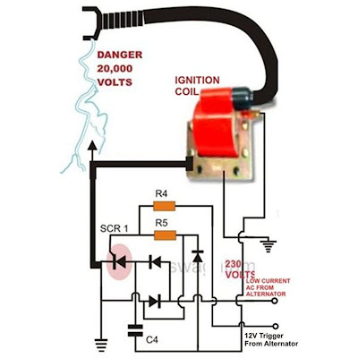
Referring to the above capacitor discharge ignition circuit diagram, we see a simple configuration consisting of a few diodes, resistors, a SCR and a single high voltage capacitor.
The input to the CDI unit is derived from two sources of the alternator.
One source is a low voltage around 12 volts while the other input is taken from the relatively high voltage tap of the alternator, generating around a 100 volts.
The 100 volts input is suitably rectified by the diodes and converted to 100 volts DC. This voltage is stored inside the high voltage capacitor instantaneously.
The low 12 voltage signal is applied to the triggering stage and used for triggering the SCR.
The SCR responds to the half wave rectified voltage and switches the capacitors ON and OFF alternately.
Now since the SCR is integrated to the ignition primary coil, the released energy from the capacitor is forcibly dumped in the primary winding of the coil.
The action generates a magnetic induction inside the coil and the input from the CDI which is high in current and voltage is further enhanced to extremely high levels at the secondary winding of the coil.
The generated voltage at the secondary of the coil may rise up to the level of many tens of thousands of volts.
This output is appropriately arranged across two closely held metal conductors inside the spark plug.
The voltage being very high in potential starts arcing across the points of the spark plug, generating the required ignition sparks for the ignition process.
Parts List for the CIRCUIT DIAGRAM
R4 = 56 Ohms,
R5 = 100 Ohms,
C4 = 1uF/250V
SCR = BT151 recommended.
All Diodes = 1N4007
Coil = Standard two-wheeler ignition Coil
Subscribe to:
Posts (Atom)