Showing posts with label inverter. Show all posts
Showing posts with label inverter. Show all posts
Tuesday, April 2, 2013
Inverter 5000 Watt PWM
This inverter uses PWM (Pulse Width Modulator) with type IC SG3524. IC serves as a oscillator 50Hz, as a regulator of the desired output voltage. Input power ranging from 250W up to 5000W output and has. Following a series INVERTER 5000W with PWM (Pulse Width Modulator).
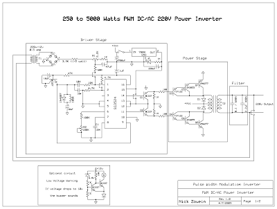 |
| Schematic Inverter 5000W with PWM (Pulse Width Modulator) |
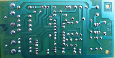 |
| Layout PCB Inverter 5000W with PWM (Pulse Width Modulator) |
below is the output power settings that can be issued by this inverter:
DC voltage and Transformer "T2" winding recommendation:
Winding Power Supply
12VDC 750W P: 24V "12-0-12" / S: 220V
1500W 24VDC P: 48V "24-0-24" / S: 220V
2250w 36VDC P: 72V "36-0-36" / S: 220V
3000w 48VDC P: 96V "48-0-48" / S: 220V
3750w 60VDC P: 120V "60-0-60" / S: 220V
4500w 72VDC P: 144V "72-0-72" / S: 220V
5250w 84VDC P: 168V "84-0-84" / S: 220V
Transformer used is the transformer CT
R1 serves to regulate the voltage to 220v inverter
R2 serves to regulate the inverter output frequency of 50 or 60 Hz (as appropriate)

Saturday, March 23, 2013
Inverter Overload Protector With Delayed Auto Rest
An overload condition in an inverter may permanently damage the power transistor array or burn off the transformer. Some of the domestic inverters sold in the market do not feature an overload shutdown facility, while those incorporating this feature come with a price tag.the circuit presented here is an overload detector which shuts down the inverter in an overload condition.
Inverter Overload Protector With Delayed Auto Rest Circuit diagram:

It hasthe following desirable features:
- It shuts down the inverter and also provides audio-visual indication of the overload condition.
- after shutdown, it automatically restarts the inverter with a delay of 6 seconds. thus, it saves the user from the inconvenience caused due to manually resetting the system or running around in darkness to reset the system at night.
- It permanently shuts down the inverter and continues to give audio warning, in case there are more than three successive overloads. Under this condition, the system has to be manually reset.(Successive overload condition indicates that the inverter output is short-circuited or a heavy current is being drawn by the connected load.)

Inverter Overload Protector With Delayed Auto Rest
The circuit uses an ammeter (0-30a) as a transducer to detect overload condition. Such an am-meter is generally present in almost all inverters. this ammeter is connected between the negative supply of the battery and the inverter, as shown in Fig. 2. the voltage developed across this ammeter, due to the flow of current, is very small. It is amplified by IC2, which is wired as a differential amplifier having a gain of 100. IC3 (NE555) is connected as a Schmitt ‘trigger’, whose output goes low when the voltage at its pin 2 exceeds 3.3V. IC4 (again an NE555 timer) is configured as a monostable multivibrator with a pulsewidth of 6 seconds. IC5 (CD4017) is a CMOS counter which counts the three overload conditions, after which the sys-tem has to be reset manually, by pressing push-to-on switch S1. the circuit can be powered from the inverter battery. In standby condition, it consumes 8-10 ma of current and around 70 mA with relay (RL1), buzzer (PZ1), and LED1 energised.
Please note the following points carefully:
- Points A and B at the input of IC2 should be connected to the corresponding points (A and B respectively) across the ammeter.
- Points C and D on the relay terminals have to be connected in series with the already existing ‘on’/‘off’ switch leads of inverter as shown in Fig. 1. this means that one of the two leads terminated on the existing switch has to be cut and the cut ends have to be connected to the pole and N/O contacts respectively of relay RL1.
- The ammeter should be connected in series with the negative terminal of the battery and inverter, as shown in Fig. 2.Move the wiper of preset VR1 to the extreme position which is grounded. Switch ‘on’ the inverter. For a 300W inverter, connect about 250-260W of load. Now adjust VR1 slowly, until the inverter just trips or shuts down. repeat the step if necessary. Use good-quality preset with dust cover (e.g. multiturn trimpot) for reliable operation.the circuit can be easily and success-fully installed with minimum modifications to the existing inverter. all the components used are cheap and readily avail-able. the whole circuit can be assembled on a general-purpose PCB. The cost of the whole circuit including relay, buzzer, and PCB does not exceed Rs 100.
Source: http://www.ecircuitslab.com/2011/11/inverter-overload-protector-with.html
Subscribe to:
Posts (Atom)